A contained biological experiment developed as a microsatellite-scale instrument, with coordinated mechanics, sensing, electronics, imaging, and reference control software.
Scope
Systems, mechanics, electronics architecture, control logic and verification planning
Stage
Narrative Rev A design exercise Digital artifacts and local software tests
Evidence
Editable CAD and recorded controller tests No physical experiment or flight
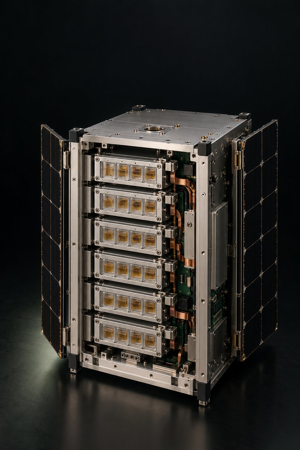
Original source concept visualization of the microsatellite-scale instrument. CAD governs the layout; this image is not a flight article or fabricated instrument.
The engineering question
How would an autonomous instrument distinguish a visible repair from a joint that actually transfers force? The study defines a sequence that creates a controlled separation, introduces an assigned repair treatment, records the interval, and measures the resulting mechanical behavior.
The membrane is the experimental specimen. Containment, cartridge handling, sensing, power, and communications remain conventional engineered subsystems. Their interfaces must preserve both the experiment and its evidence.
Three decisions that shaped the system
Separate imaging from actuation
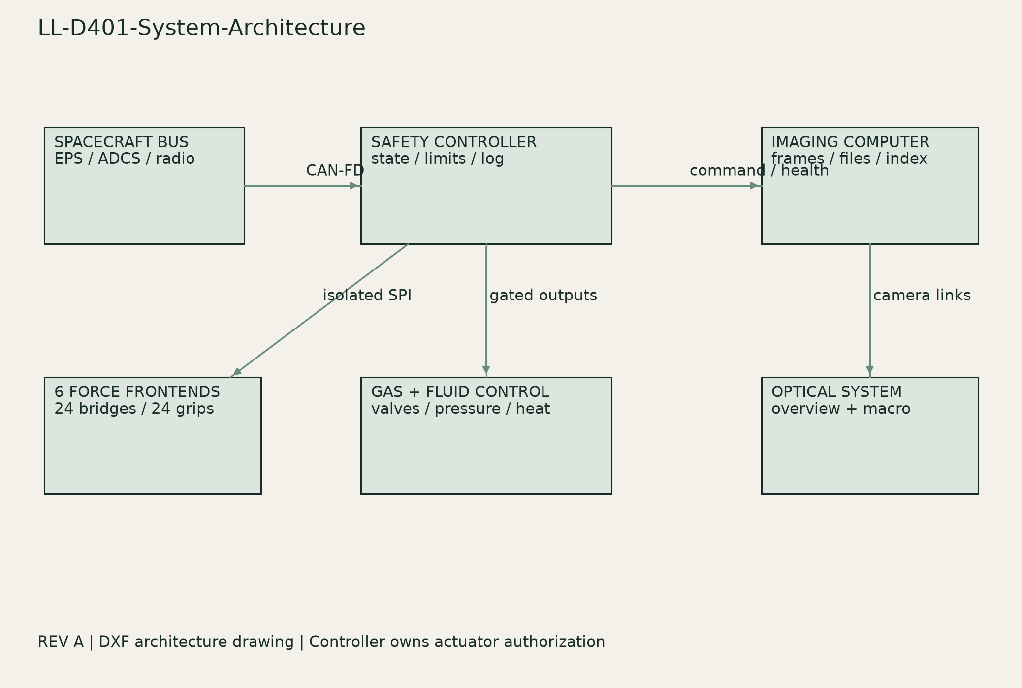
The safety controller owns motion, valves, and measurement. A separate imaging computer owns cameras and files. Camera readiness is a prerequisite for a scheduled damage event; camera or storage failure cannot grant authority to operate the blade.
Make the cartridge the traceable unit
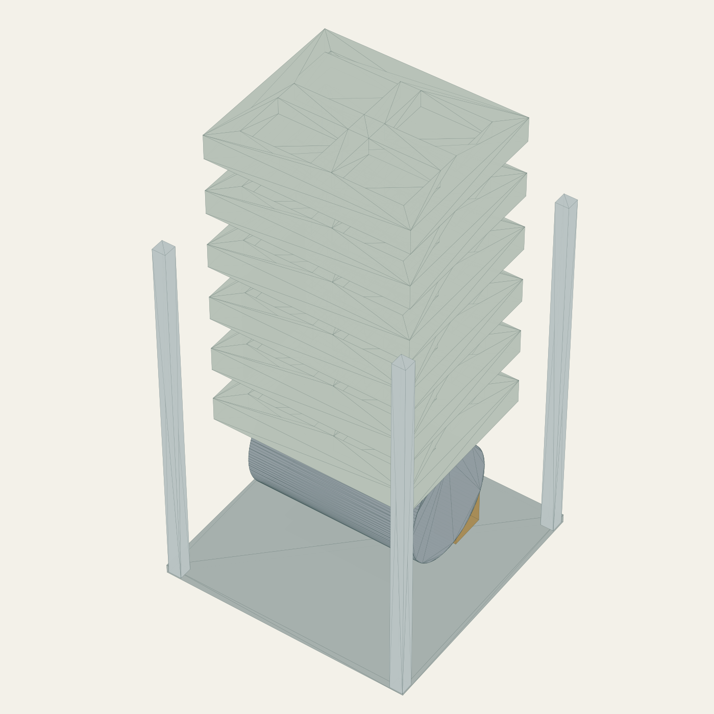
The selected layout contains 24 specimens in six four-position cassettes. Cartridge identity connects commands, images, calibration, and raw force samples. A failed channel remains a failed observation rather than being replaced with a more favorable result.
Coordinate the operating schedule with resource limits
Only one cartridge undergoes mechanical testing at a time. High-load activities depend on a power grant. Imaging cadence, heating, storage, and measurement are considered together. The specification’s power and mass figures are analytical allocations, awaiting physical and mission-specific closure.
Architecture drawing from the supplied design package. Independent control and imaging domains exchange permission, readiness, timing, and evidence records.Exploded view derived from the editable assembly CAD. Layout geometry represents a digital design baseline; it does not demonstrate assembly clearances, fabrication readiness, or physical hardware.
From architecture to editable artifacts
The package moves beyond a product rendering into files that can be examined and developed further: STEP assembly models, DXF drawings, three electronics placement floorplans, a software data path, a firmware state-machine definition, and a behavioral reference controller.
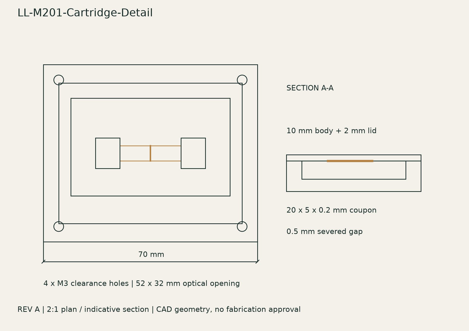
Cartridge detail from the native DXF drawing. The geometry establishes a layout for grips, specimen, and movement; tolerance closure, pressure containment, and calibrated force behavior remain physical engineering tasks.
What was demonstrated
30 behavioral controller tests passed in the package’s recorded local Python run.
Five STEP files were re-imported and checked for valid solids.
Eleven DXF drawings were read back and audited without reported errors.
These results support the digital artifacts and reference behavior. They do not validate flight firmware, physical interlocks, biological repair, force accuracy, or environmental qualification.
The next verification gates
Workstream
Evidence needed before advancing
Measurement
Traceable force calibration, grip and interface offsets, converter behavior, and repeatable raw-to-corrected data.
Biology and containment
Ground repair experiments, inactive controls, batch repeatability, storage viability, and provider-reviewed leak and retention requirements.
Electronics and mechanics
Component-level schematics, real footprints, routed PCB design, bench tests, clearance and tolerance analysis, and fabrication review.
Mission integration
Orbit-dependent power and link analysis, environmental tests, mission endurance, and host or launch-provider acceptance.
The source is a narrative design exercise, not a customer delivery or flight mission. KiCad artifacts are unconnected placement floorplans, not released boards. Illustrative biological traces in the original specification are synthetic and are not used here as performance evidence.
Source basis: Living Loom Design Specification, LL-SPEC-001 Rev A, 14 October 2026; companion README, CAD validation records, and software test record. This editorial study summarizes the supplied digital package and its stated evidence limits.
Developing an instrument with demanding subsystem interfaces?